Embedded development with Ivory Tower
\[\forall dev \in embedded . dev \Join ivory = \heartsuit\]
1 Overview
The goal of this book is to provide comprehensive guide to embedded development with Ivory Language and its Tower framework. If you feel like there is much to be desired from the currently available embededded toolchains keep on reading!
1.1 Ivory
The Ivory Language is an embedded domain specific language (eDSL) for safe systems programming. It is embedded in Haskell which keeps types in check and serves as a macro language. Ivory can generate various outputs - most notably a C code.
1.2 Tower
Tower is a framework written in Ivory for composing Ivory programs in safe manner - by providing communication channels, tasks, signal handlers and scheduling. Tower uses low level primitives from either FreeRTOS or EChronos embedded real-time operating systems.
1.3 Target board
The board we are going to use throughout this book is STM32 F4 Discovery. This is quite nice development board featuring STM32F407VG microcontroller (MCU), few peripherals like MEMS accelerometer and a smaller STM32F103 MCU for programming the main MCU.
Most of the STM32 MCUs are now suppported, check out ivory-tower-stm32-generated compatibility matrix.
2 Environment setup
Recommend development environment is a NixOS system as we use Nix to setup all the required dependencies and even build full firmware images. NixOS system is not strictly required but Nix is (it can be installed on most systems either via their native package manager or according to https://nixos.org/manual/nix/stable/#ch-installing-binary).
After Nix installation, clone ivory-tower-nix repository which contains our Haskell overlay and recipes for building various firmware images and development shells.
git clone https://github.com/HaskellEmbedded/ivory-tower-nix/
git clone https://github.com/distrap/ivory-tower-helloworld/
cd ivory-tower-nix
nix-shell
cd ../ivory-tower-helloworld
make simpleblink-test
2.1 Repositories
mkdir embedded
cd embedded
git clone https://github.com/GaloisInc/ivory/
git clone https://github.com/GaloisInc/tower/
git clone https://github.com/GaloisInc/ivory-tower-stm32/
2.2 Programmer
For F4 Discovery it is recommended to re-flash ST-Link programmer with BlackMagic probe and add UART passthru according to F4 Discovery hacking section
2.3 UDev
For persistent device names you should create udev rules files in /etc/udev/rules.d/. For example to create rules for your F4 Discovery board flashed with Black Magic probe firmware you can use the following template:
# F4 Discovery
SUBSYSTEMS=="usb", ATTRS{manufacturer}=="Black Sphere Technologies", ATTRS{serial}!="E3C09CF4", GOTO="f4_bmp_end"
ACTION=="add", SUBSYSTEM=="tty", ATTRS{interface}=="Black Magic GDB Server", MODE="0660", GROUP="dialout", SYMLINK+="f4gdb"
ACTION=="add", SUBSYSTEM=="tty", ATTRS{interface}=="Black Magic UART Port", MODE="0660", GROUP="dialout", SYMLINK+="f4uart"
LABEL="f4_bmp_end"
Make sure to set correct serial number, this can be found by running dmesg after the board is plugged in.
Create similar file as /etc/udev/rules.d/48-bmp.rules and run
udevadm control -Rto reload UDev daemon. Next time you plug in your device two nodes should be created
/dev/f4gdb- for attaching GDB/dev/f4uart- UART2 pass-through
2.4 Accessing UART
Following are few examples of UART access from Linux:
# miniterm.py from pyserial
miniterm.py -e /dev/f4uart 115200

# screen
screen /dev/f4uart 115200

# tail + hexdump
tail -f /dev/f4uart | hexdump -C
3 Hello Ivory Tower world
Go to your embedded directory and clone ivory-tower-helloworld repository.
git clone https://github.com/distrap/ivory-tower-helloworldNow build and flash a blink application:
cd ivory-tower-helloworld
make blink-test-run
Makefile uses /dev/ttyACM0 by default - to change this either override this on the command line
make TARGET=/dev/f4dev blink-test-runor change the TARGET ?= /dev/ttyACM0 line in Makefile.
If all goes well your board should toggle red and blue LEDs in 1 second and 666 milliseconds intervals.
Before we dive deeper into what is going on try playing with the uart test.
Open another terminal and start screen
screen /dev/ttyACM1 115200
# or /dev/f4uart if you defined u-dev rules according to example
Flash board with
make uart-test-runYou should get a prompt on screen terminal similar to the following
hello world
tower>
The uart application accepts 1 2 and \n (newline) characters. 1 sets the LED on, 2 off and newline displays prompt again.
The Makefile offers additional targets
make uart-test # only compiles app
make uart-test-load # also loads it to MCU
make uart-test-gdb # loads it and spawns gdb prompt where application can be 'start'ed
make uart-test-run # combines load and 'run'
3.1 simpleblink dissected
To explain the structure of the application we will use simpleblink application, which is quite simplified blink example we had ran previously. This contrived example is only for demonstration purposes and it outlines basic concepts of Ivory/Tower.
The core of the simpleblink app is the file Hello.Tests.SimpleBlink which we will explain step-by-step.
{-# LANGUAGE DataKinds #-}

module Hello.Tests.SimpleBlink where

import Ivory.Language
import Ivory.Tower
import Ivory.HW.Module

import Ivory.BSP.STM32.Peripheral.GPIOF4
First the obligatory module and imports, the two most important imports here are Ivory.Language and Ivory.Tower modules, the former imports Ivory definitions and the latter for Tower framework. We also need to import Ivory.HW.Module as our module does some hardware manipulation, in this case writing to GPIO registers of F4 devices. Definitions of the GPIO registers are imported from Ivory.BSP.STM32.Peripheral.GPIOF4 (the application actually uses only GPIOPin type from this module as the rest of the GPIO manipulation is abstracted).
We also need to enable DataKinds language extension to allow for complex type annotations of our towers. Following tower represents a block of code responsible for toggling a led. Its type tells us a that it accepts a GPIOPin and returns a ChanInput ('Stored ITime)) in the Tower monad which basically means that by creating this tower it gives us an input channel with some concrete type (in this case ITime).
-- This artificial Tower program toggles LED when
-- message arrives on its channel
ledToggle :: GPIOPin -> Tower e (ChanInput ('Stored ITime))
ledToggle ledPin = do
  -- Create a channel for communicating with this tower
  (cIn, cOut) <- channel
By using channel function we create a channel with input and output sides. We proceed by defining a monitor with some name. Monitor is another building block we will meet quite frequently and its exact meaning will be explained later.
  monitor "ledToggle" $ do
    -- declare dependency on Ivory.HW.Module.hw_moduledef
    monitorModuleDef $ hw_moduledef
For the monitor to work properly we need to declare its dependency on a module containing primitives for reading and writing hardware registers. The module is hw_moduledef imported from Ivory.HW.Module.
After the book-keeping is done we proceed by defining two handlers grouped within our monitor. The first handler is called once during system initialization and prepares our hardware for operation - in this cases enables ledPin and configures it as an output pin.
    -- handler called during system initialization
    handler systemInit "initLED" $ do
      callback $ const $ do
        pinEnable ledPin
        pinSetMode ledPin gpio_mode_output
handler is a function that accepts a channel output, handler name in form of a string and a handler definition in Handler monad. In Handler monad we use a callback function to define an actual code used for handling channel messages. callback accepts another function which on message arrival gets a reference to the message. Because we don’t care about the type of the systemInit channel we throw away the reference with const. systemInit is the only global channel provided by Tower. The actual body of the callback function consists of Ivory code which in this case is quite abstracted to just pinEnable and pinSetMode functions. Next handler is a bit more interesting.
    -- LED state
    ledOn <- stateInit "ledOn" (ival false)

    -- handler for channel output
    handler cOut "toggleLED" $ do
      callback $ const $ do
        -- get current state
        isOn <- deref ledOn

        ifte_ isOn
          (do
            pinClear ledPin
            store ledOn false
          )
          (do
            pinSet ledPin
            store ledOn true
          )
In monitor context, we first define a ledOn state with stateInit function. To be explicit we also define its initialization value via ival false hence the use of stateInit instead of simpler state function that would also initialize ledOn state variable to false after its type is inferred from local context. We will discuss state and initializers in more detail a bit later.
ledOn represents a local state variable contained within current monitor. We use this to track the current state of the LED and flip it with the second handler. Note that this is the only state variable so far.
Handler and callback for cOut channel we have defined earlier are defined in similar fashion to the previous handler except now we have more Ivory code in body of our function.
On message reception we first use deref function to dereference our ledOn state variable. Then we branch according to its value with ifte_ function which is basically a C equivalent of if. Depending on the value we either clear or set the LED and use store function to store our new LED state in ledOn variable. To perform actual register writes we use pinSet and pinClear functions that operate on respective GPIO registers for ledPin GPIO.
Last missing piece of our ledToggle tower is a return function returning input side of the channel we have created previously.
Now when our LED toggling tower is complete we define another tower that represents our application and which uses the ledTower. It is common to call this tower app as it represents an entry point of our application. It also accepts a function of type e -> GPIOPin which is used to pass a part of the environment to our application respective of the platform we run on (different platforms can specify different peripherals and pin mappings while our code can be made completely independent of the used platform). We then extract ledpin with toledpin function from the environment given by getEnv.
Then we start composing towers. We create a period tower with per channel output and also our ledToggle tower with togIn control channel. What remains now is to forward messages from per channel to togIn channel to make our LED controller react on periodic messages generated by period tower. For this we write a simple monitor that defines an emitter for togIn input channel. We then use the created emitter togInEmitter in callbacks body to send messages to it via emit function. Callback function now accepts a parameter x which is a reference to ITime message produced by period tower. We don’t really care about its contents so we just send it to ledToggle tower via togInEmitter and togIn channel input.
-- main Tower of our application
app :: (e -> GPIOPin) -> Tower e ()
app toledpin = do
  ledpin <- fmap toledpin getEnv

  -- creates a period that fires every 500ms
  -- `per` is a ChanOutput, specifically ChanOutput ('Stored ITime)
  per <- period (Milliseconds 500)

  -- create our ledToggle tower
  togIn <- ledToggle ledpin

  -- this monitor simply forwards `per` messages to `togIn` ChanInput
  monitor "blink" $ do
    handler per "blinkPeriod" $ do
      -- message to `togIn` channel are sent via `togInEmitter` - FIFO with capacity 1
      togInEmitter <- emitter togIn 1

      -- callback for period
      callback $ \x ->
        emit togInEmitter x
This contrived example doesn’t really show the full power of Tower and Ivory but only illustrates basic concepts of structuring applications and passing messages to different parts of the application. Following figure illustrates the structure of our application:
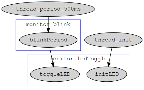
3.2 blink comparison
simpleblink is a simplified version of blink application that goes even further regarding abstractions and defines a following ledController function:
ledController :: [LED] -> ChanOutput ('Stored IBool) -> Monitor e ()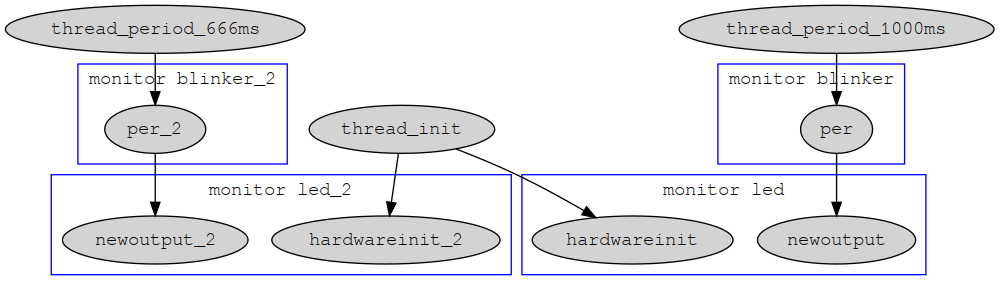
From the type of the ledController you can infer a lot of information about the controller - it accepts a list of LEDs and an output side of a IBool typed channel. You might guess the functionality and it’s usage just by looking at the type information - by feeding a boolean value to input side of the channel, the ledController switches a bunch of LEDs according to the received value.
4 Compilation
Entry points of the helloworld applications can be found in the test directory as this was originally extracted from ivory-bsp-tests (ivory-tower-stm32 repository). These are not complete applications anyway and during development you will write many of such test applications testing a small part of the complete system.
If we take a look test/SimpleBlinkTest.hs we can see few mandatory imports that allow us to set-up the environment according to selected platform from default.conf config file.
All the magic happens in the compileTowerSTM32FreeRTOS function provided by Ivory.OS.FreeRTOS.Tower.STM32.
Imports of our code follow - Platforms (basically mapping to hardware) and app from SimpleBlink module.
module Main where

import Ivory.Tower.Config
import Ivory.Tower.Options
import Ivory.OS.FreeRTOS.Tower.STM32

import Hello.Tests.Platforms
import Hello.Tests.SimpleBlink (app)

main :: IO ()
main = compileTowerSTM32FreeRTOS testplatform_stm32 p $
  app testplatform_ledpin
  where
  p :: TOpts -> IO TestPlatform
  p topts = getConfig topts testPlatformParser
Application typically accepts a number of functions of type e -> Something which are used for querying environment with getEnv. This allows to use the same application with different platforms and configurations. In case of simpleblink we only pass a testplatform_ledpin to app as it only needs one GPIOPin to work.
5 Platforms
5.1 Clock config
6 GDB basics
Printing register data
p /t 0x8000Printing MSB bit of rxdata.rx_buf[0] contents shifted by 8 bits to the left
p /t (rxdata.rx_buf[0] << 8) & 0b10000000000000006.1 .gdbinit
Is your friend
set confirm off
set history save on
set mem inaccessible-by-default off

display /x txcmd
display /x rxcmd

display cnt

display /x rxcmd.rx_buf
display /t rxcmd.rx_buf
7 Ivory
Ivory is a fully featured eDSL for safe system programming. Ivory gives strong guarantees of type and memory safety. It can be regarded as a restricted variant of C language.
7.1 Casts
When converting numbers from one type to another we have to do it explicitly - there is no automatic conversion and failure to cast numbers will result in type errors.
Ivory provides us with few casting operations: safeCast, signCast, bitCast, castWith, castDefault, twosComplementCast
These are restricted by type classes so for example SafeCast only allows us to cast smaller Uint8 to larger Uint16 but not vice-versa.
7.1.1 SafeCast
SafeCast typeclass represents conversions that can be done safely
- from smaller (bitwise) integers to its larger counterparts
Uint8toUint16or largerSint8toSint16or larger
- from unsigned integers to signed integers
Uint8toSint16- but not
Uint8toSint8
- from floats to doubles
IFloattoIDouble
- from integers to floats or doubles
Uint16toIFloatorIDoubleSint32toIFloatorIDouble- with the exception of
Uint64/Sint64that can only be converted toIDouble
Example use:
x <- assign (23 :: Uint8)
y <- assign $ (safeCast :: Uint8 -> Sint32) x
Often we don’t have to specify the type of safeCast and let the compiler infer the conversion according to surrounding code.
7.1.2 SignCast
SignCast allows us to convert numbers with the same bitwidth from unsigned to their signed counterparts iff the conversion is safe. If the conversion would result in overflow its result is the minimum or maximum boundary of the target type. Same holds for converting signed to unsigned numbers.
Examples include
signCast :: Sint8 -> Uint8
signCast :: Uint64 -> Sint64
7.1.3 bitCast
To cast from larget bit type to smaller one, while discarding upper bits of the input we can use bitCast. This is only valid for unsigned integer types.
Examples:
bitCast :: Uint16 -> Uint8
bitCast :: Uint64 -> Uint8
7.1.4 castWith and castDefault
We can use castWith defaultValue to cast a value if it is within boundaries of the target type or fallback to defaultValue if it is outside bounds.
castDefault is like castWith 0 for types where 0 value is defined (types having Default typeclass).
7.1.5 twosComplementCast
To convert between signed and unsigned types of the same width, we can use twosComplementCast which will convert values bitwise, e.g. from Uint32 to Sint32.
7.2 Bit twiddling
Lots of embedded code revolves around bit manipulation. In the end even the most complex embedded applications are just setting a bunch of registers so we need a nice tooling for this important part of our job.
Ivory offers bitdata quasi-quoter for defining binary layouts. This is used heavily in device drivers and for controlling registers of the STM32 MCU.
[ivory|
 bitdata MyReg :: Bits 16 = my_reg
   { myreg_bit_rw   :: Bit
   , myreg_bit_crc  :: Bit
   , myreg_bit_mode :: Bits 2
   , myreg_data     :: Bits 12
   }
|]
Lets see what this produces:
> :t MyReg
MyReg :: Bits 16 -> MyReg

> :i
newtype MyReg = MyReg (Bits 16)

(x :: MyReg) = fromRep $ withBits 0 $ setBit myreg_bit_crc

y = toRep x

> :t y
Uint16
We can convert from integer value to binary representation with fromRep and back to integer with toRep.
7.2.1 Bit representation
-- | Type function: "BitRep (n :: Nat)" returns an Ivory type given a
-- bit size as a type-level natural.  Instances of this type family
-- for bits [1..64] are generated using Template Haskell.

(fromRep (1 :: Uint8) :: Bit)
(fromRep (1 :: Uint8) :: Bits 4)

-- can't do this (Couldn't match type ‘Uint16’ with ‘Uint8’)
(fromRep (1 :: Uint16) :: Bits 8)

-- instead we need
(fromRep (1 :: Uint16) :: Bits 9)
-- BitDataRep moves to next possible representation for 9 bits which is Uint16
7.3 ivory-hw
ivory-hw package offers utilities for defining and working with registers. Hardware registers are associated with BitData types from previous section via BitDataReg type.
7.3.1 Defining registers
There are two functions for creating BitDataReg types
mkBitDataReg :: IvoryIOReg (BitDataRep d) => Integer -> BitDataReg d
mkBitDataRegNamed :: IvoryIOReg (BitDataRep d) => Integer -> String -> BitDataReg d
We can see that a type d needs to have a BitDataRep instance for BitDataReg to be created. Second parameter is an actual memory address of the register and a String in case of Named version is just for identifying registers in AST or comments in generated code.
To define a register we first need to define a bitdata using ivory quasi-quoter. We will use an actual register definition of 32-bit advanced timer shared memory controller register (ATIM_SMCR).
[ivory|
 bitdata ATIM_SMCR  :: Bits 32 = atim_smcr
  { _               :: Bits 16
  , atim_smcr_etp   :: Bit
  , atim_smcr_ece   :: Bit
  , atim_smcr_etps  :: Bits 2
  , atim_smcr_etf   :: Bits 4
  , atim_smcr_msm   :: Bit
  , atim_smcr_ts    :: Bits 3
  , _               :: Bit
  , atim_smcr_sms   :: Bits 3
  }
|]


myreg = (mkBitDataReg 0x1337) :: BitDataReg ATIM_SMCR
-- or
myreg = (mkBitDataRegNamed 0x1337 "adc_sr") :: BitDataReg ATIM_SMCR
Most of the time we don’t need to define this directly but we instead create a new type representing a certain peripheral composed of all the peripherals registers. Before explaining this structuring further lets see how we can access and modify such registers.
7.3.2 Modifying registers
Most common method of working with registers is modifyReg which accepts a register and a code in BitDataM monad. For example to set the MSM bit and clear the ETP bit we would write
modifyReg myreg $ do
  setBit atim_smcr_msm
  clearBit atim_smcr_etp
In case of fields consisting of multiple bits we need to use a setField function. For example to set ETF field to number 1 we would write
modifyReg myreg $ do
  setField atim_smcr_etf $ fromRep 1
In this case we also need to use fromRep to convert our number to its binary representation.
7.3.3 Setting registers
To set a register instead of modifying it you can use a setReg function.
setReg myreg $ do
  setBit atim_smcr_msm
  setBit atim_smcr_ece
  setField atim_smcr_etf $ fromRep 1
myreg is in this case replaced with newly built value.
7.3.4 Reading registers
For reading we have a getReg function and an infix operator (#.) for accessing bit data fields (similar to Data.Lens.^.).
x <- getReg myreg
when (bitToBool (x #. atim_smcr_msm)) $ do
  ...
To extract a value from a multi-bit field we would write
x <- getReg myreg
let val <- toRep (x #. atim_smcr_etf)

-- :t val
-- Uint8
7.3.5 Device peripheral driver structure
reg :: (IvoryIOReg (BitDataRep d)) => Integer -> String -> BitDataReg d
reg offs name = mkBitDataRegNamed (base + offs) (n ++ "->" ++ name)
7.4 Types
7.4.1 Boolean
IBool
7.4.2 Char
IChar
7.4.3 Numeric types
Uint8 - 64 Sint8 - 64
7.4.3.1 Floating
IFloat IDouble
7.4.4 Memory area types
Stored X Array n X Struct “name”
7.4.5 Pointer types
Ref Local (Stored Sint32) Ref Global (Struct “foo”) Ref s (Stored IBool)
7.4.6 Initializer types
Init x
7.4.7 Index types
Ix n support 0 .. n-1 values
example (10 :: Ix 11)
7.5 Initializers
ival izero
7.6 Structs
To create structs we use a quasi-quoter provided by Ivory.Language. Following example is a definition of a Measurement struct.
{-# LANGUAGE DataKinds #-}
{-# LANGUAGE QuasiQuotes #-}
{-# LANGUAGE FlexibleInstances #-}
{-# OPTIONS_GHC -fno-warn-orphans #-}

module Hello.Types where

import Ivory.Language
import Ivory.Tower.Types.Time

[ivory|
struct measurement
  { meas_valid :: Stored IBool
  ; meas_data  :: Array 3 (Stored Uint32)
  ; meas_time  :: Stored ITime
  }
|]

measTypesModule :: Module
measTypesModule = package "meas_types" $ do
  defStruct (Proxy :: Proxy "measurement")
The function measTypesModule creates a Module (XXX: Refer to module system) which we can use to declare a dependency on this measurement struct.
7.6.1 Struct initialization
To create a new struct we use istruct initializer, most commonly in combination with local such as:
t <- getTime

res <- local $ istruct [
    meas_valid .= ival true
  , meas_time  .= ival t
  ]
res now contains a memory reference to our newly created “measurement” struct, its type is
> :t res
Ref s ('Struct "measurement")
7.7 Struct access
To get a value out of structs field use deref in combination with ~> operator:
valid <- deref $ res ~> meas_validTo set a field we use store and ~>:
store (res ~> meas_valid) false~> operator is just a field access operator according to the label passed on its right side, as the fields of the struct are all Stored values we can use deref and store to alter these.
(XXX: Link to ~>* shortcut
7.8 Statements
7.8.1 Loops
for (n-1) times (n-1) upTo downTo
7.8.2 Conditionals
ifte cond cond_ when unless
Boolean ops ==? /=? <? >? <=? >=?
.&& .|| iNot
7.9 Functions
7.10 Comments
7.11 Modules
7.12 Standard library
7.12.1 Operators
~>*
%=
%=!
+=
7.12.1.1 Bit manipulation
AND .&
OR  .|
XOR .^
<< iShiftL
>> iShiftR
iComplement
7.12.2 Arrays
arrayCopy7.12.3 Maybe
7.12.4 Working with strings
String is just an alias for struct with two fields
stringDataL- actual string contentsstringLengthL- length of the currently stored string
Define string with the help of Ivory quasi quoter:
{-# LANGUAGE QuasiQuotes #-}
{-# LANGUAGE DataKinds #-}
{-# LANGUAGE FlexibleInstances #-}
{-# LANGUAGE TypeFamilies #-}
{-# OPTIONS_GHC -fno-warn-orphans #-}

module FW.Types where

[ivory| string struct TestBuffer 1024 |]

fwTypes :: Module
fwTypes = package "c4dTypes" $ do
  defStringType (Proxy :: Proxy TestBuffer)

fwTowerDeps :: Tower e ()
fwTowerDeps = do
  towerDepends fwTypes
  towerModule fwTypes
This creates a TestBuffer type with IvoryString typeclass with maximum capacity of 1024 characters. We also define two helper functions fwTypes and fwTowerDeps to provide shortcuts for dependency management.
Strings are commonly used as buffers for UART communication. You can also initialize string directly with
myStr <- stringInit "foo"7.13 Serialization
Ivory.Serialize Ivory.Serialize.Little
8 Tower
The Tower Language is a concurrency framework for composing Ivory programs into real-time systems. Tower offers communication channels, signal handlers, tasks and scheduling.
8.1 Structure of a tower
Following is an overly verbose tower definition with comments explaining different contexts and general outline of a tower. sampleTower is a fake controller which takes an output channel and returns another output channel called control. Incoming values are passed to control channel iff their value is over 9000.
sampleTower :: ChanOutput ('Stored Uint8)
            -> Tower e (ChanOutput ('Stored Uint8))
sampleTower outChan = do
  {-
  Here we can define additional channels, towers and periods (which are also towers)
  -}
  (controlInChan, controlOutChan) <- channel

  {-
  Afterwards we define a monitor - which basically defines a controller block
  -}
  monitor "sampleMonitor" $ do
    {-
    In monitor we can define its states
    -}
    lastValue <- state "lastValue"

    {-
    and a handler for our input channel
    -}
    handler outChan "sampleMonitorIn" $ do
      {-
      in handler, we can define its emitters, to be used for writing into channels (ChanInput(s))
      -}
      controlEmitter <- emitter controlInChan 1
      {-
      Then we write actual callback function
      that gets `ref` passed from `outChan`s output

      In this case this is a reference to `Uint8` so we
      need to use `deref` to get a value  we can store
      and compare later - if the value is over 9000 we
      use `emit` to emit the same reference as we've
      received from callback via controlEmitter.
      -}
      callback $ \ref -> do
        value <- deref ref
        store lastValue value

        when (value >? 9000) $ emit controlEmitter ref

  return controlOutChan
8.2 Channels
Tower gives us two types representing communication channels
ChanInput a- typed channel used to send messages of typeaChanOuput a- typed channel used to receive message of typea
We use channel function to create a channel, which is just a tuple of input and output sides.
chan <- channel
(chanIn, chanOut) <- channel
We typically structure our program as a network of channels and respective handlers and emitters. In the previous example of sampleTower we have a function that accepts ChanOutput ('Stored Uint8) and returns another channel of the same type.
This tells us that the tower receives messages from one channel and gives us a channel that we can use to consume messages produced by it. It also creates the latter channel for us and returns its output side. Does this remind you of the UNIX pipes?
8.3 Periods
Tower gives us a way of scheduling periodic events via messages generated on some channel. period function gives us a channel of type ChanOutput ('Stored ITime) which we can use in our handlers where periodic calls are required.
periodic <- period (Milliseconds 500)
-- per <- period (Microseconds 1000)

monitor "sampleMonitor" $ do
  handler periodic "samplePeriod" $ do
    callback $ const $ return ()
8.4 Interrupts
For working with interrupts Tower offers the signalUnsafe function, which accepts the actual interrupt, time bound (or deadline) for real time verification purposes and a function for disabling the interrupt. When interrupt occurs it automatically calls the disable function and we need to enable the interrupt again if deserved.
isrExampleTower :: (STM32Interrupt i)
                => i
                -> Tower e ()
isrExampleTower int = do
  irq <- signalUnsafe
            (Interrupt int)
            (Microseconds 250)
            (interrupt_disable int)

  monitor "isrExampleMon" $ do
    handler isr "isrHandler" $ do
      callback $ const $ do
        -- we serve the interrupt here
        -- and reenable it afterwards
        interrupt_enable int
8.5 HAL
HAL or Hardware Abstraction Layer in Tower is an extremely small interface abstracting over common embedded communication buses like SPI, I2C or CAN.
Module Ivory.Tower.HAL.Bus.Interface defines two higher order types, BackpressureTransmit and AbortableTransmit. At first these look quite complicated and scary but they are nothing more than a representation of a way of how we talk to the peripheral driver.
8.5.1 BackpressureTransmit
Commonly used as BackpressureTransmit request response for SPI and I2C buses. We send message to backpressureTransmit channel and receive responses from backpressureComplete channel.
data BackpressureTransmit value status = BackpressureTransmit
  { backpressureTransmit :: ChanInput value
  , backpressureComplete :: ChanOutput status
  }
8.5.2 AbortableTransmit
AbortableTransmit is used for communication over CAN bus where it is possible to abort the pending transfer before it is sent to the bus. This is useful for cases where we have e.g. more recent measurement available but our last message is still waiting to be transferred - we can abort the transfer and send the more recent message instead.
This is similar to BackpressureTransmit but offers abortableAbort channel, which can be used to cancel the transfer.
data AbortableTransmit value status = AbortableTransmit
  { abortableTransmit :: ChanInput value
  , abortableAbort :: ChanInput ('Stored IBool)
  , abortableComplete :: ChanOutput status
  }
8.6 Coroutines
Coroutines allow us to suspend and resume a computation, typically while waiting for result of another computation. This is very handy for embedded programming as we often need to wait for external device to return new data over some channel.
For example when we communicate with some device connected over UART we just use a channels provided by UART driver to talk to it and let the driver do all the hard work of actually transmitting bytes and letting us know when transmission is complete.
Coroutine allows us to call a yield function which it provides for us to pause the execution and wait for a result of a computation tied to yield.
Following is a simple hypothetical example which uses three channels: * initChan - channel used to initialize or restart the coroutine * requestChan - we use this one to send requests * resultChan - we get results of our computation over this channel
yield in CoroutineBody is then tied to resultChan and gets called whenever we get a message on that channel.
coroutineHandler initChan resultChan "myCoroutine" $ do

  requestEmitter <- emitter chan 1

  return $ CoroutineBody $ \yield -> do
    emitV requestEmitter true
    fstResult <- yield

    emitV requestEmitter false
    sndResult <- yield

    return ()
This is quite useful for protocol oriented communication with devices connected over UART, SPI, I2C or CAN bus - we send a request message, wait for a driver to handle transport for us and sends us a reply over result channel - which triggers respective yield in our coroutine.
Take for example UART driver - it typically returns two channels, one for output and for input. We use the output channel (usually named ostream) to send data to the external device and input channel (typically istream) to receive the data.
We can take advantage of this in our coroutines where we use output channel to send messages to external device via emitter and yield to wait for replies.
Lets say we want to implement simple request reply protocol in form of
> version
< 1
> readbit
< 0
We can use the following coroutine to perform the communication:
protocolTower :: ChanInput ('Stored Uint8)
              -> ChanOutput ('Stored Uint8)
              -> Tower p ()
protocolTower ostream istream = do
  monitor "protocol" $ do
    coroutineHandler systemInit istream "myProtocolCoroutine" $ do

      requestEmitter <- emitter ostream 32

      return $ CoroutineBody $ \yield -> do

        puts requestEmitter "version"
        versionResult <- yield

        puts requestEmitter "readbit"
        bitValue <- yield

        return ()
SPI device drivers are implemented in similar manner but instead of ostream and istream they operate with
BackpressureTransmit ('Struct "spi_transaction_request")
                     ('Struct "spi_transaction_result")
In this case we need to fill a struct representing our SPI request and we get back another struct with the result of the SPI transfer. This pattern is commonly expressed as rpc function which calls a function to create our request, send it to device and wait (with yield) for the result.
Following is an example of simple SPI device driver that reads out a specific register and sends true on initOkChan if we see an expected value (common pattern during device installation is to check some vendor provided register if it contains a correct value so we know we are talking to the right device).
devDriver :: BackpressureTransmit ('Struct "spi_transaction_request")
                                  ('Struct "spi_transaction_result")
          -> ChanOutput ('Stored ITime)
          -> ChanInput  ('Stored IBool)
          -> SPIDeviceHandle
          -> Tower e ()
devDriver :: (BackpressureTransmit reqChan resChan) initChan initOkChan dev = do
  monitor "devMonitor" $ do

    coroutineHandler initChan resChan "devDriver" $ do
      reqE <- emitter reqChan 1
      doneE <- emitter initOkChan 1

      return $ CoroutineBody $ \yield -> do
        let rpc req = req >>= emit reqE >> yield

        contents <- rpc (readRegReq dev 0x05)
        fstByte <- deref ((contents ~> rx_buf) ! 1)
        emitV doneE (fstByte ==? 0x13)

-- here we construct a spi_transaction_request struct
readRegReq :: (GetAlloc eff ~ 'Scope s)
           => SPIDeviceHandle
           -> Uint8
           -> Ivory eff (ConstRef ('Stack s) ('Struct "spi_transaction_request"))
readRegReq dev reg = fmap constRef $ local $ istruct
  [ tx_device .= ival dev
  , tx_buf    .= iarray [ ival (fromIntegral reg), ival 0 ]
  , tx_len    .= ival 2
  ]
8.7 Schedule
Ivory.Tower.HAL.Bus.Sched
Citing from schedules docstring
-- | Multiplex a request/response bus across any number of tasks that
-- need to share it. Tasks may submit requests at any time, but only one
-- task's request will be submitted to the bus at a time. When that
-- request's response arrives, it is forwarded to the appropriate task
-- and the next waiting task's request is sent.
--
-- If multiple tasks have outstanding requests simultaneously, then this
-- component will choose the highest-priority task first. Earlier tasks
-- in the list given to 'schedule' are given higher priority.
8.8 Drivers
uartDriver i2cDriver canDriver
9 Driver tutorial
9.1 forever
forever :: Ivory (E.AllowBreak eff) () -> Ivory eff ()
^^ noBreak needed sometimes due to this, forever $ noBreak $ do
10 App tutorial
11 Porting
We start adding stuff to ivory-tower-stm32 repository and all the paths here are relative to this repository.
When adding a new CPU you first need to add your CPU to Processor data type and also to processorParser in ivory-bsp-stm32/src/Ivory/BSP/STM32/Processor.hs.
Then you need to create stm32fXXXDefaults function in ivory-bsp-stm32/src/Ivory/BSP/STM32/Config.hs. Make sure to adjust stm32config_sram (used in FreeRTOS.total_heap_size) and stm32config_clock - if using external crystal this calls another function
externalXtal xtal_mhz 168where 168 is the target frequency in Mhz. Definition of externalXtal is part of ivory-bsp-stm32/src/Ivory/BSP/STM32/ClockConfig.hs file. In ivory-bsp-stm32/src/Ivory/BSP/STM32/ClockConfig/Init.hs resides an actual clock initialization function init_clocks which you might need to alter if not using internal oscillator (HSI) or external crystal (HSE).
Now we will add our CPU to ivory-bsp-stm32/src/Ivory/BSP/STM32/LinkerScript.hs which contains a linker_script function with several cases according to CPU. Add another attrs STM32XXX section and make sure you sram_length and ccsram_length are set correctly. CCSRAM corresponds to core-coupled memory which is tightly coupled to CPU to allow for code execution at maximum frequency. Templated linker script is located in ivory-bsp-stm32/support/linker_script.lds.template and might need adjusting as well (sram and ccsram origins are hardcoded for now).
11.1 Unoffical ports
We created few unofficial ports for F0, F1, F3 and F334 families which probably won’t be integrated to ivory-tower-stm32 unless there’s significant interest. Porting from F3 was quite easy but the port is far from complete, similar to F1 and F0 ports.
During the development of hexamon firmware for STM32F042 we’ve managed to hit the limits of the MCU quite fast and had to limit the number of actual FreeRTOS tasks spawned. While Ivory/Tower can run on such small MCU with only 6Kb of SRAM and 32Kb of flash it severally limits your options and should be considered for only single purpose applications. We also had to decrease FreeRTOS stack size for all of our tasks to be created. If you are still interested in this port you can take a look at Initial F0 commit.
Currently we are trying to port to newer F7 and L4 families which we would like to use in our projects and support along with original F4 support.
12 Tower backends
12.1 Posix
13 Gidl
14 Projects using Ivory/Tower
14.1 SMACCMPilot
14.2 DistRap
14.3 hexamon
15 Further reading
16 opts
17 Enums
Ivory doesn’t provide quasi-quoter for enums so we need to define these manually. We first define the type and derive typeclasses and the create a bunch of concrete instances for further usage.
newtype MotorState = MotorState Uint8
  deriving (IvoryType, IvoryVar, IvoryExpr, IvoryEq, IvoryStore, IvoryInit, IvoryZeroVal)

motorStopped, motorStarting, motorRunning, motorBreaking :: MotorState
[motorStopped, motorStarting, motorRunning, motorBreaking] = map (MotorState . fromInteger) [0..3]
18 Structs
[ivory|
  struct motor {
    motorState    :: Stored MotorState
  ; motorVelocity :: Stored Uint32
  ; motorPosition :: Stored IFloat
  ; motorEnabled  :: Stored IBool
  }
|]

motorTypes :: Module
motorTypes :: package "motor_types" $ do
  defStruct (Proxy :: Proxy "motor")

motorTowerDeps :: Tower e ()
motorTowerDeps = do
  towerDepends motorTypes
  towerModule motorTypes
Initialization
state <- stateInit "motor_state" (
  istruct [
      motorPosition .= ival 123
    , motorEnabled  .= True
  ])
Missing fields from istruct are initialized to IvoryZeroVal which is most often 0 or False.
UNSORTED
spiData :: (GetAlloc eff ~ 'Scope s)
        => SPIDeviceHandle
        -> AS5407Data
        -> Ivory eff (ConstRef ('Stack s) ('Struct "spi_transaction_request"))
spiData dev msg = fmap constRef $ local $ istruct
  [ tx_device .= ival dev
  , tx_buf    .= iarray [h msg, l msg]
  , tx_len    .= ival 2
  ]
  where l x = ival $ bitCast $ toRep x
        h x = ival $ bitCast $ (toRep x) `iShiftR` 8


--- how
dat <- spiData dev (as5407Msg ..)
emit reqE dat
reply <- yield
CONVERTING FROM REGISTER TO STRUKT
diagFromRegs :: Uint16 -> Ref s ('Struct "ams_diag") -> Ivory eff ()
diagFromRegs x r = do
  p magfield_low        as_diag_magl
  p magfield_high       as_diag_magh
  p cordic_overflow     as_diag_cof
  p offset_compensation as_diag_lf
  store (r ~> agc_value) (toRep (fromRep x #. as_diag_agc))
  where
    p lbl field = store (r ~> lbl) (bitToBool (fromRep x #. field))

MON
diag <- state "diag"

FOLLOWING SPI REQUEST

x <- yield
hi <- deref ((x ~> rx_buf) ! 0)
lo <- deref ((x ~> rx_buf) ! 1)
u16dat <- assign $ (((safeCast hi `iShiftL` 8) .| safeCast lo) :: Uint16)
diagFromRegs u16dat diag
//CONVERTING FROM REGISTER TO STRUKT
PACKING WRAPPERS
{-# LANGUAGE DataKinds #-}
{-# LANGUAGE TypeOperators #-}
{-# LANGUAGE QuasiQuotes #-}
{-# LANGUAGE TypeFamilies #-}
{-# LANGUAGE FlexibleContexts #-}
{-# LANGUAGE FlexibleInstances #-}
{-# LANGUAGE ScopedTypeVariables #-}
{-# LANGUAGE GeneralizedNewtypeDeriving #-}
{-# LANGUAGE RecordWildCards #-}

module ODrive.Types where

import Ivory.Language
import Ivory.Tower
import Ivory.Serialize

[ivory|
struct adc_sample
  { vbus    :: Stored IFloat
  ; phase_b :: Stored IFloat
  ; phase_c :: Stored IFloat
  ; meas_t  :: Stored ITime
  }

struct svm_out
  { svm_a :: Stored IFloat
  ; svm_b :: Stored IFloat
  ; svm_c :: Stored IFloat
  ; svm_sextant :: Stored IFloat
  }
|]

-- from SMACCMPilot.Flight.Control.PID
-- | Constrain a floating point value to the range [xmin..xmax].
fconstrain :: Def ('[IFloat, IFloat, IFloat] ':-> IFloat)
fconstrain = proc "fconstrain" $ \xmin xmax x -> body $
  (ifte_ (x <? xmin)
    (ret xmin)
    (ifte_ (x >? xmax)
      (ret xmax)
      (ret x)))

odrive_types :: Module
odrive_types = package "odrive_types" $ do
  defStruct (Proxy :: Proxy "adc_sample")
  defStruct (Proxy :: Proxy "svm_out")
  depend serializeModule
  wrappedPackMod svmOutWrapper
  incl fconstrain

svmOutWrapper :: WrappedPackRep ('Struct "svm_out")
svmOutWrapper = wrapPackRep "svm_out" $
  packStruct
  [ packLabel svm_a
  , packLabel svm_b
  , packLabel svm_c
  , packLabel svm_sextant
  ]

instance Packable ('Struct "svm_out") where
  packRep = wrappedPackRep svmOutWrapper
19 F4 Discovery hacking
Following section outlines few convenience hacks that can be done on F4 Discovery boards.
19.1 BlackMagic probe
The F4 Discovery board comes with ST-Link programmer firmware flashed on STM32F103 MCU. We can replace this firmware with opensource BlackMagic probe (BMP) firmware that allows us to use GDB directly without support tools like OpenOCD or stlink. This requires few simple hardware modifications although if you are not good with soldering small components better ask a friend for help. First we prepare the board for BMP flashing and then we add UART pass-through.
19.1.1 Flashing
Remove solder bridges SB3, SB5, SB7, SB9 and close bridges SB2, SB4, SB6, SB8. Switching these from default to reserved enables flashing STM32F103 MCU via ST-LINK port.
Next remove jumpers from ST-LINK port and jumper JP1 connecting target MCU to programmer MCU. Connect external programmer to ST-LINK port - pin 1 is marked with dot:
Pin 1 - 3V3
Pin 2 - SWCLK
Pin 3 - GND
Pin 4 - SWDIO
To see device states during the process it is useful to open a second terminal and run
dmesg -HwNext build firmware for stlink target and upload it to target
# make PROBE_HOST=stlink
# flashing blackmagic_dfu via black magic probe
git clone https://github.com/blacksphere/blackmagic/
cd blackmagic
make PROBE_HOST=stlink
arm-none-eabi-gdb --ex 'target extended-remote /dev/ttyACM0' src/blackmagic_dfu
# in GDB
monitor swdp_scan
attach 1
monitor option erase
# RESTART target so it unlocks, repeat up to 'monitor option erase' then issue
load
# RESTART target, it should boot to black magic dfu
# [  +0.000002] usb 1-1.2: Product: Black Magic (Upgrade) for STLink/Discovery, (Firmware v1.6-rc0-257-gd6e2977)
# upload black magic via dfu
#
# disconnect your programmer so only target board is connected
#
sudo dfu-util -s 0x08002000:leave -D src/blackmagic.bin
# if dfu-util can't find your device you can specify -S <serial> from dmesg output
sudo dfu-util -S 7EBA7BA4 -s 0x08002000:leave -D src/blackmagic.bin
Sample session:
$ arm-none-eabi-gdb --ex 'target extended-remote /dev/ttyACM0' src/blackmagic_dfu
Reading symbols from src/blackmagic_dfu...done.
Remote debugging using /dev/ttyACM0
(gdb) monitor swdp_scan
Target voltage: unknown
Available Targets:
No. Att Driver
 1      STM32F1 medium density
(gdb) attach 1
Attaching to program: /home/rmarko/embedded/blackmagic/src/blackmagic_dfu, Remote target
0x08010064 in ?? ()
(gdb) monitor option erase
0x1FFFF800: 0x0000
0x1FFFF802: 0x0000
0x1FFFF804: 0x0000
0x1FFFF806: 0x0000
0x1FFFF808: 0x0000
0x1FFFF80A: 0x0000
0x1FFFF80C: 0x0000
0x1FFFF80E: 0x0000
(gdb) load
Error erasing flash with vFlashErase packet
# ^^ target needs rebooting to unlock flash
(gdb) quit

# <TARGET REBOOTED>

$ arm-none-eabi-gdb --ex 'target extended-remote /dev/ttyACM0' src/blackmagic_dfu
Reading symbols from src/blackmagic_dfu...done.
Remote debugging using /dev/ttyACM0
(gdb) monitor swdp_scan
Target voltage: unknown
Available Targets:
No. Att Driver
 1      STM32F1 medium density
(gdb) attach 1
Attaching to program: /home/rmarko/embedded/blackmagic/src/blackmagic_dfu, Remote target
0xfffffffe in ?? ()
(gdb) load
Loading section .text, size 0x1c48 lma 0x8000000
Loading section .data, size 0x90 lma 0x8001c48
Start address 0x8001498, load size 7384
Transfer rate: 11 KB/sec, 820 bytes/write.
(gdb) quit

# <TARGET REBOOTED>

$ dmesg
[691195.851258] usb 1-1.6: new full-speed USB device number 112 using ehci-pci
[691195.943994] usb 1-1.6: New USB device found, idVendor=1d50, idProduct=6017
[691195.943997] usb 1-1.6: New USB device strings: Mfr=1, Product=2, SerialNumber=3
[691195.943999] usb 1-1.6: Product: Black Magic (Upgrade) for STLink/Discovery, (Firmware v1.6.1-98-g9a5b31c)
[691195.944001] usb 1-1.6: Manufacturer: Black Sphere Technologies
[691195.944002] usb 1-1.6: SerialNumber: 7EBA7BA4

$ sudo dfu-util -S 7EBA7BA4 -s 0x08002000:leave -D src/blackmagic.bin
dfu-util 0.9

Copyright 2005-2009 Weston Schmidt, Harald Welte and OpenMoko Inc.
Copyright 2010-2016 Tormod Volden and Stefan Schmidt
This program is Free Software and has ABSOLUTELY NO WARRANTY
Please report bugs to http://sourceforge.net/p/dfu-util/tickets/

dfu-util: Invalid DFU suffix signature
dfu-util: A valid DFU suffix will be required in a future dfu-util release!!!
Opening DFU capable USB device...
ID 1d50:6017
Run-time device DFU version 011a
Claiming USB DFU Interface...
Setting Alternate Setting #0 ...
Determining device status: state = dfuIDLE, status = 0
dfuIDLE, continuing
DFU mode device DFU version 011a
Device returned transfer size 1024
DfuSe interface name: "Internal Flash   "
Downloading to address = 0x08002000, size = 60660
Download    [=========================] 100%        60660 bytes
Download done.
File downloaded successfully
Transitioning to dfuMANIFEST state
Now jumper JP1 should be put back after DFU upgrade so BlackMagic firmware doesn’t jump to DFU upgrade anymore.
# <JUMPER JP1 PUT BACK, TARGET REBOOTED>
$ dmesg
[691227.339977] usb 1-1.6: new full-speed USB device number 113 using ehci-pci
[691227.432954] usb 1-1.6: New USB device found, idVendor=1d50, idProduct=6018
[691227.432956] usb 1-1.6: New USB device strings: Mfr=1, Product=2, SerialNumber=3
[691227.432957] usb 1-1.6: Product: Black Magic Probe (STLINK), (Firmware v1.6.1-98-g9a5b31c)
[691227.432958] usb 1-1.6: Manufacturer: Black Sphere Technologies
[691227.432959] usb 1-1.6: SerialNumber: 7EBA7BA4
[691227.433654] cdc_acm 1-1.6:1.0: ttyACM0: USB ACM device
[691227.434290] cdc_acm 1-1.6:1.2: ttyACM1: USB ACM device
At this point, to be able to flash target MCU, you need to reverse solder bridge configuration we did earlier - from reserved back to default.
19.1.2 Usage
arm-none-eabi-gdb --ex 'target extended-remote /dev/ttyACM0'
# Use following commands when in gdb
monitor swdp_scan
attach 1
Sample session:
(gdb) monitor swdp_scan
Target voltage: unknown
Available Targets:
No. Att Driver
1      STM32F4xx
(gdb) attach 1
Attaching to Remote target
Error while running hook_stop:
Invalid type combination in equality test.
0x080035c2 in ?? ()
(gdb) bt
#0  0x080035c2 in ?? ()
#1  0x08001032 in ?? ()
#2  0x08001032 in ?? ()
Backtrace stopped: previous frame identical to this frame (corrupt stack?)
19.1.3 UART pass-through
To enable UART bridge from F4 discovery board to BMP enabled programmer you need to solder wires between UART2 (PA2/PA3) on STM32F407 to pins PA2/PA3 on STM32F103. These are located in the corners of the chips. Take care when soldering PA3 on F407 as it’s positioned near VSS, if you manage to short these pins try lifting PA3 from the pad completely and then soldering wire directly to it.
To access serial bridge:
screen /dev/ttyACM1 11520020 Papers
Lock Optimization for Hoare Monitors in Real-Time Systems https://www.cs.indiana.edu/%7Elepike/pub_pages/acsd17.html